Menu
RADIOS
ACCESSORIES
AUDIO
ANTENNAS
BATTERIES
BOXES
CHARGERS
CONNECTORS
CONTACT
LINKS
MISC
Harness Boxes
In larger vehicles the Clansman Radios were interconnected by an audio harness using a 12-core cable and a series of connection boxes. The Clansman harness is different from the Larkspur harness in that some functions (e.g. remote operation) are inherent in the radios, and different connectors and cables are used. I believe there is a Clansman harness box for interfacing to Larkspur radios but I have not seen it.A basic Harness installation consists of one interface box to which the radios and power input are connected and multiple crew boxes to which audio equipment is connected.
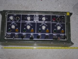
Radios and power are connected to the Interconnect Box (IB2 or IB3) and audio equipment are connected to the crew boxes.
Radios intended for use with harness have a 7-pin chassis plug pinned as follows (taken from the RT353 technical description):
| |
|
|
| |
|
|
| |
|
|
| |
|
|
| |
|
|
| |
|
|
| |
|
|
| |
|
|
Note that on the 353 some pins have different usage in data modes. In voice mode there is no separate PTT line and the radio is placed in transmit mode by connecting a low impedance (1 or 2 Kohms being the interface box audio transformer and a series resistor) across the microphone lines.
Radios not intended for harness (RT344, RT320 and RT351/2) can be connected using an Interface Box Harness Adapter (IBHA).
The 12 pin cable between the boxes carries the microphone and audio output for three radios - it is a bus. PTT keying is impedance based and the PTT for a radio is triggered by placing a low impedance across its microphone lines.
The Clansman Harness boxes and cables are described in EMER L802 part 1 available to members from VMARS.
The harness cable uses a 12-pin connector see: http://www.wealdelectronics.com/docs/lmf_lmg_connectors.pdf Page 44.
The connector pinout is:
| |
|
| |
|
| |
|
| |
|
| |
|
| |
|
| |
|
| |
|
| |
|
| |
|
| |
|
| |
|
| |
|
Microphone signals are from the crew box to the interface box. Transmitter Keying is by placing a resistance of 1.6K Ohms across the respective radio microphone pair.
In the case of a three-radio system there is a 2nd 12-way cable between the interface box and the crew boxes called ATIC carrying A-Set, C-Set and Intercom signals.
The harness boxes known to this author as of July 2009 are:
- 3 Way LT Box
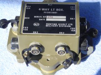
- 4 Way LT Box
- 15 Way LT Box
- Audio amplifier box
- CB2 - Crew Box 2 set
- CB3 - Crew Box 3 Set
- Commanders Personal Unit (CPU)
- CRL/R - Provides remote interface via audio socket
Can be used to add rebroadcast to the HF radios. - Drivers Box
- IB2 - Interface Box 2 Set
- IB3 - Interface Box 3 Set
- IB12 - a junction box for 12 way harness cable.
- IB - Initiate Box - used with RT351/2 to control TUAAM/ARFAT
- IBHA - Interface Box Harness Adapter
Allows manpack radios to be connected to a vehicle harness.