


The Clansman Radio System
The EVHF Antenna
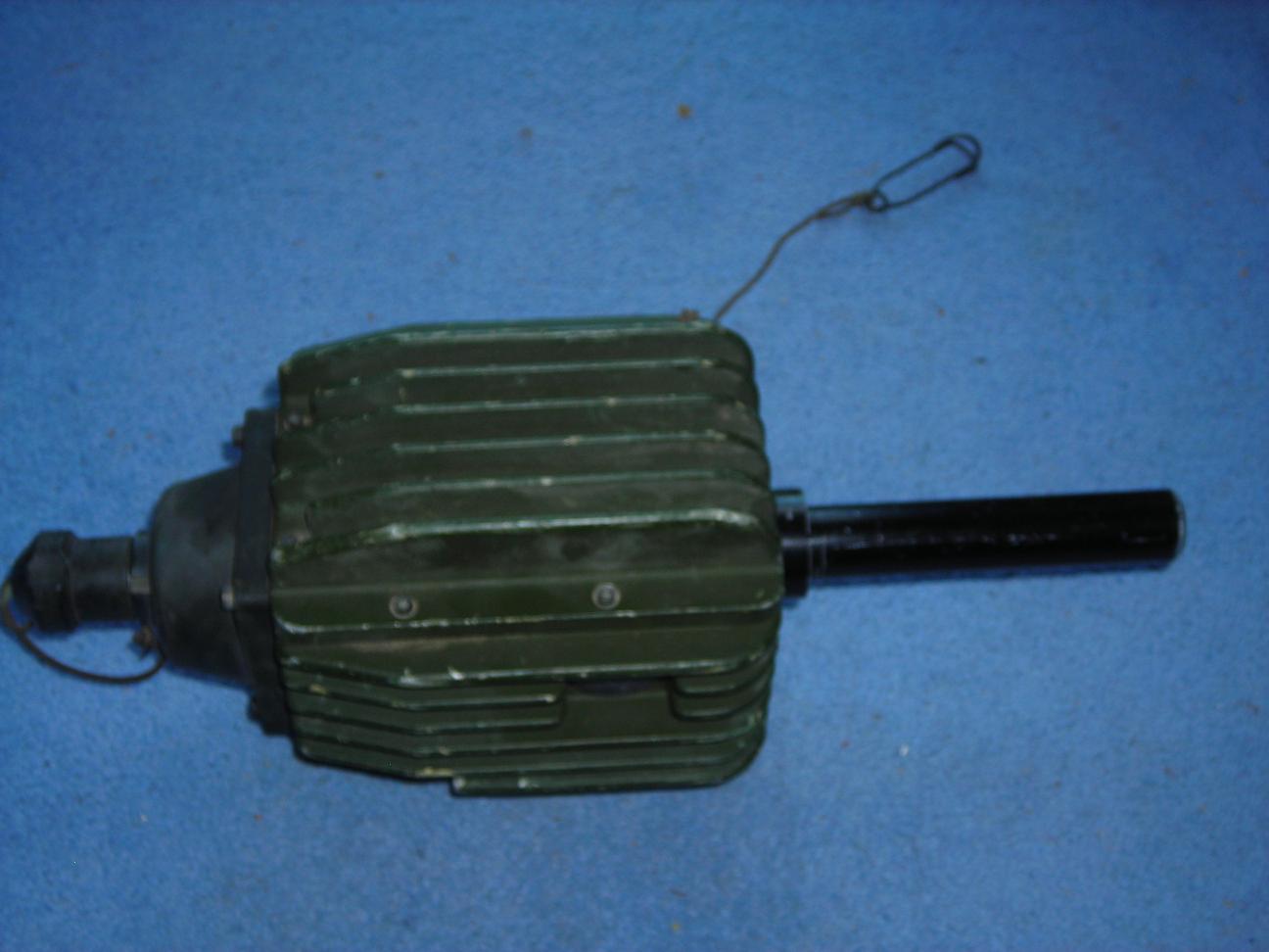
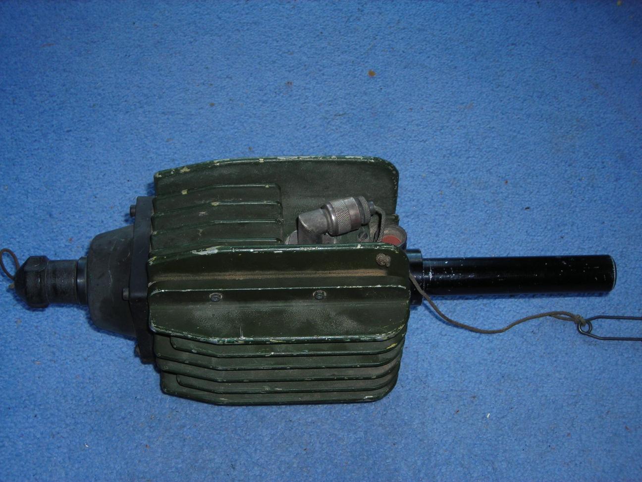
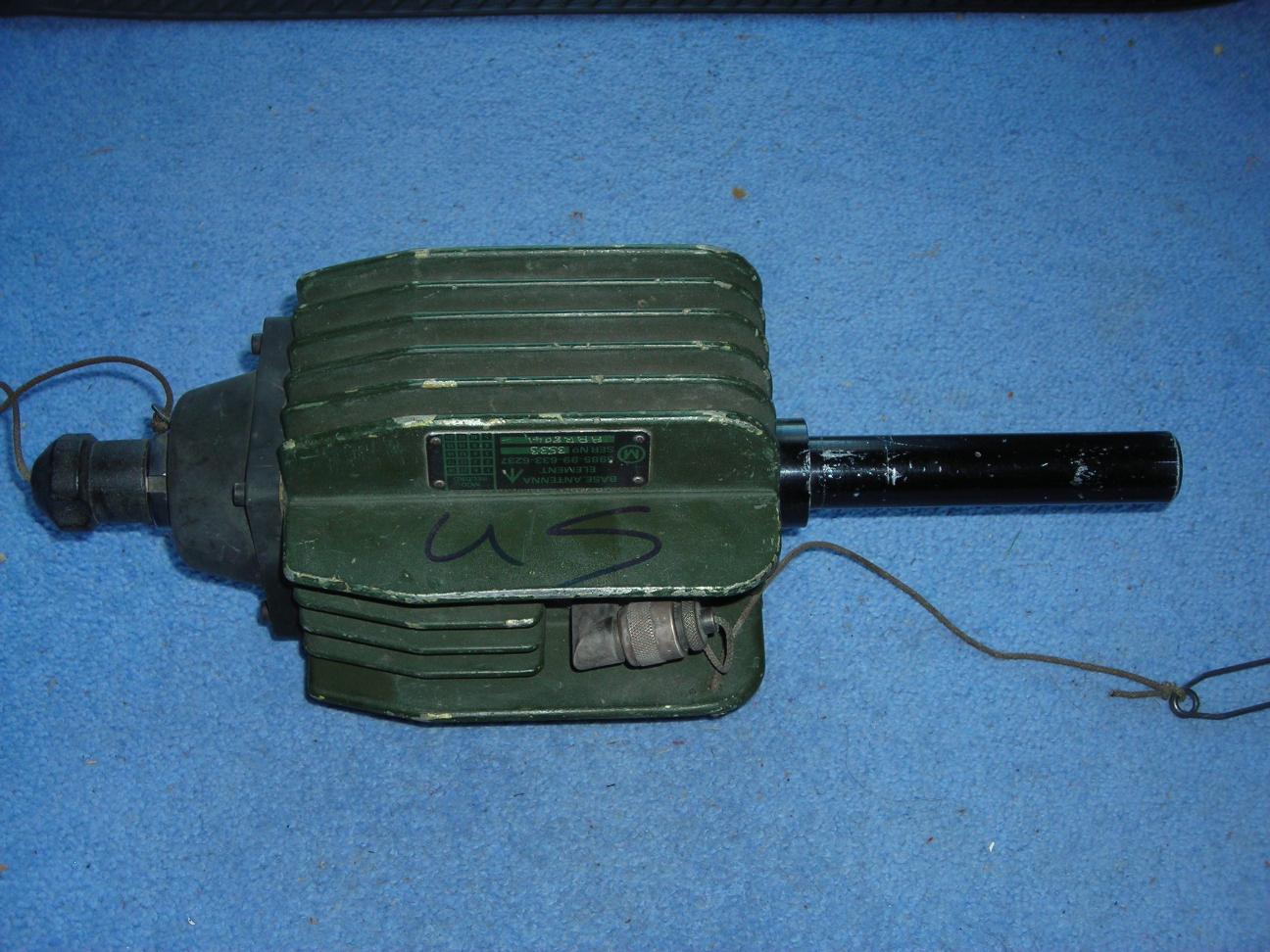
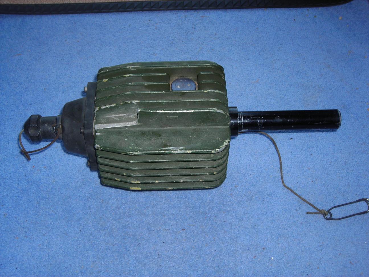
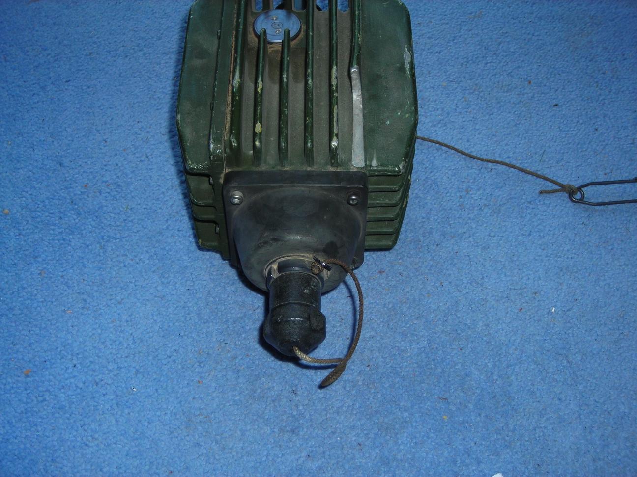
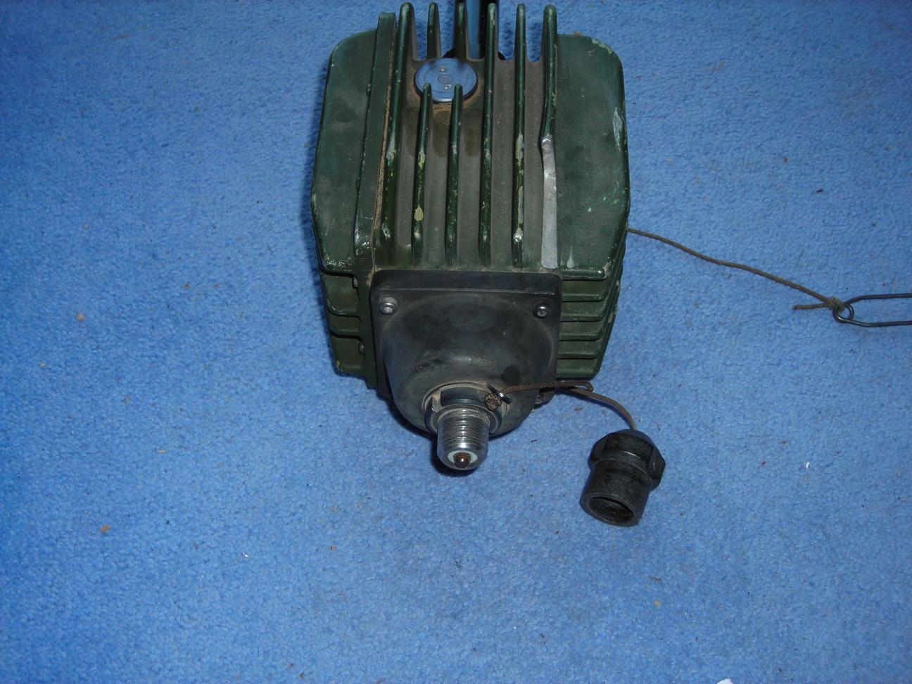
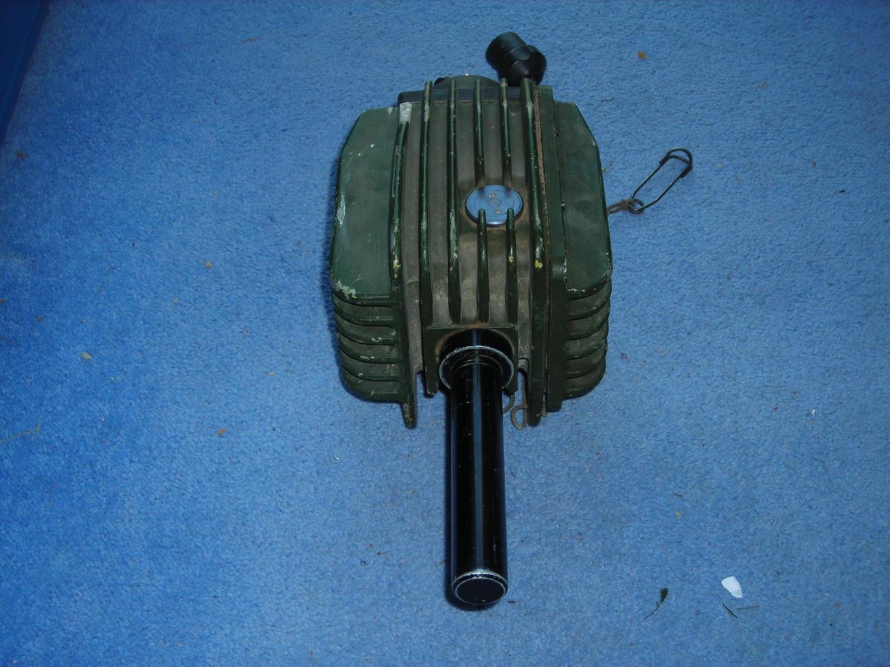
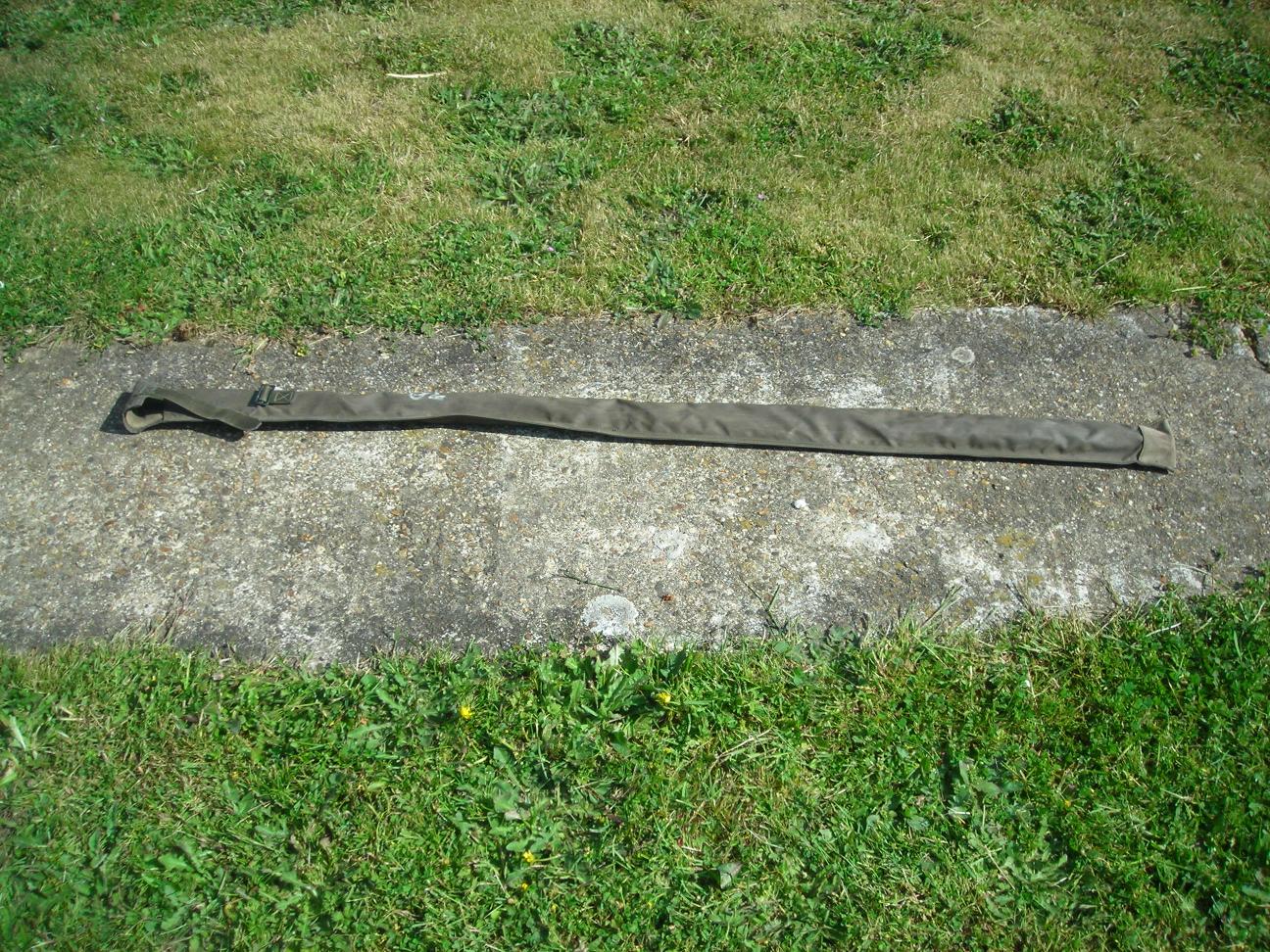
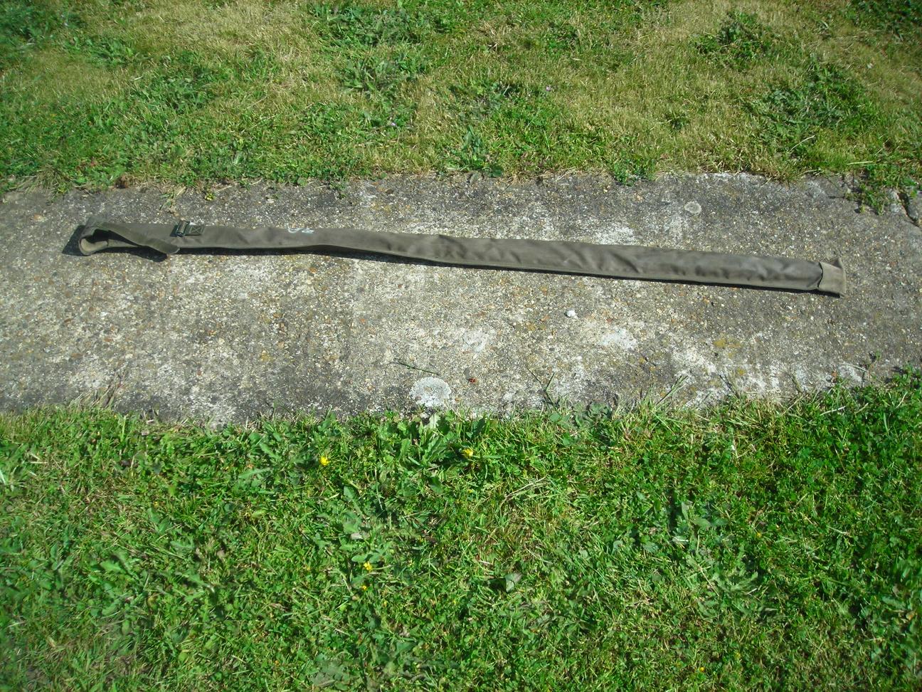
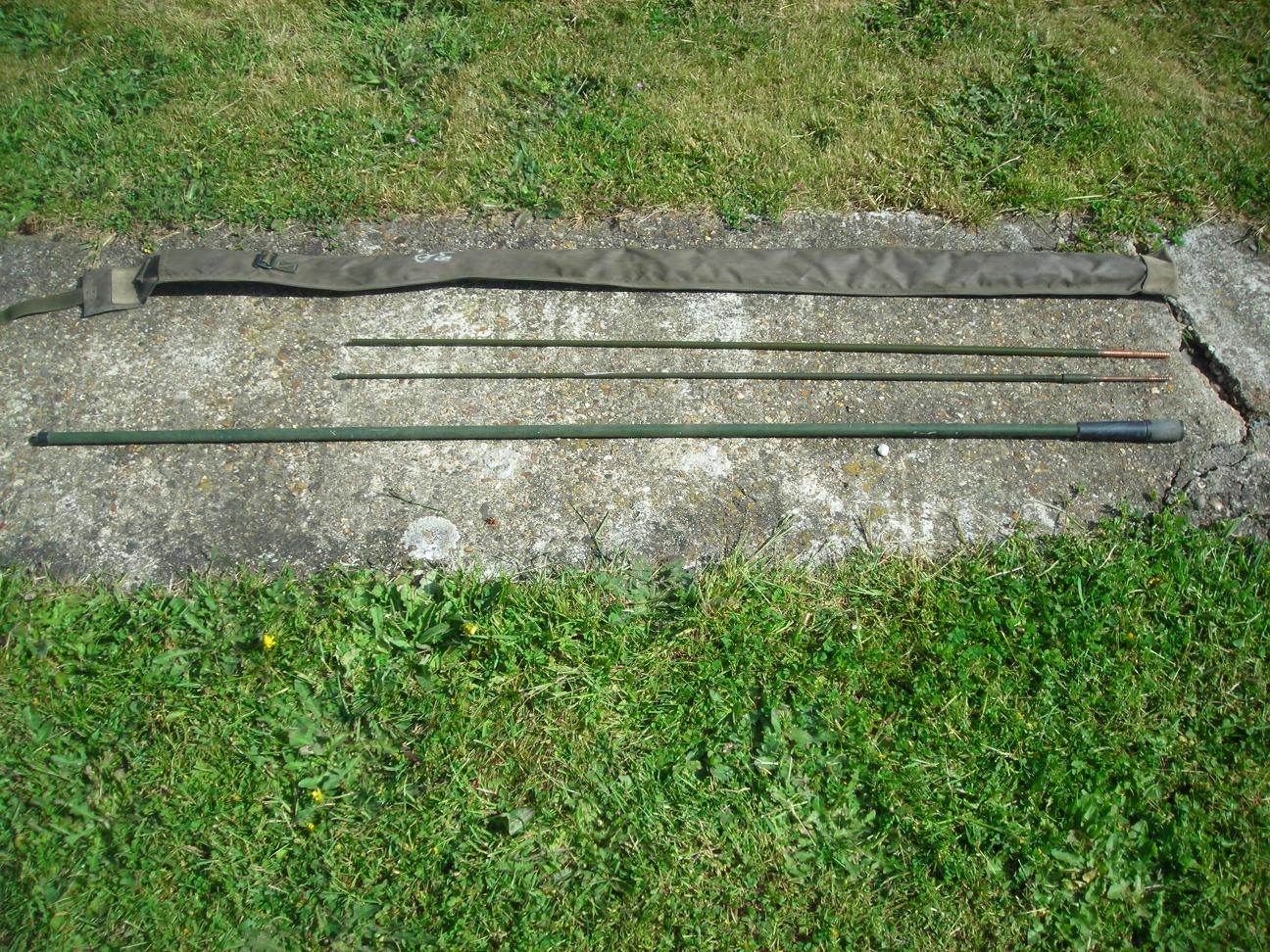
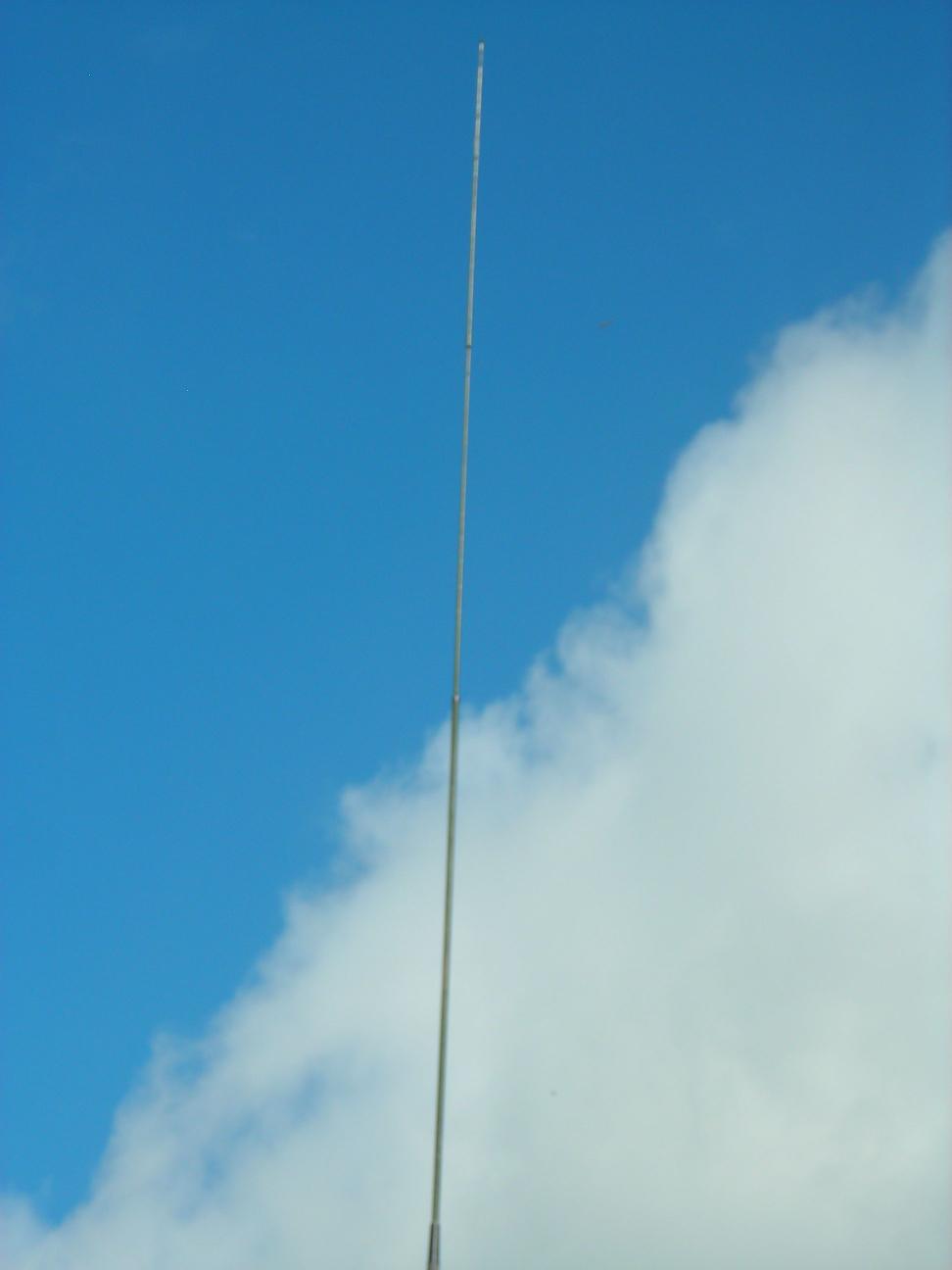
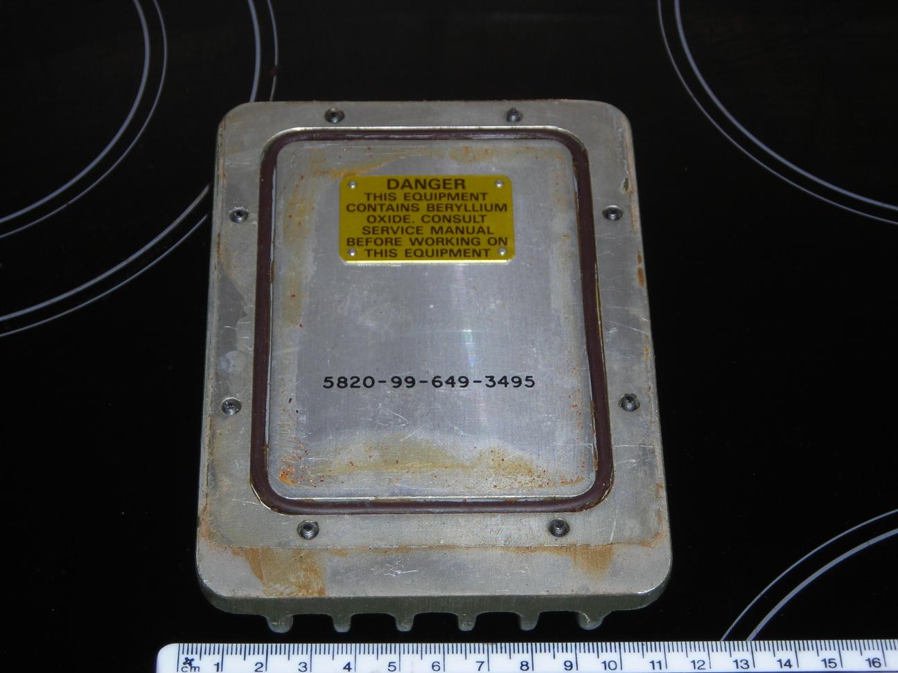
The EVHF is a broadband vertical antenna suitable for use with all the Clansman VHF sets except RT349. It is an elevated antenna intended for use on an 8m mast although I have managed to put one up on the lower half of a 5.4m fibreglass mast. No additional tuner is needed and it has a C-connector suitable for the Clansman heavy duty Coax.The antenna consists of a base unit (the "Pineapple") and three elements which screw together. The complete kit is made up of two bags - one containing the elements and one containing:
- The Pineapple base unit
- One length of low loss coax with C-Connectors
- One length of lightweight coax with BNC connectors
- One C to BNC adapter
Circuit Description
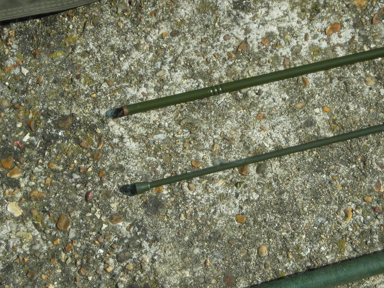
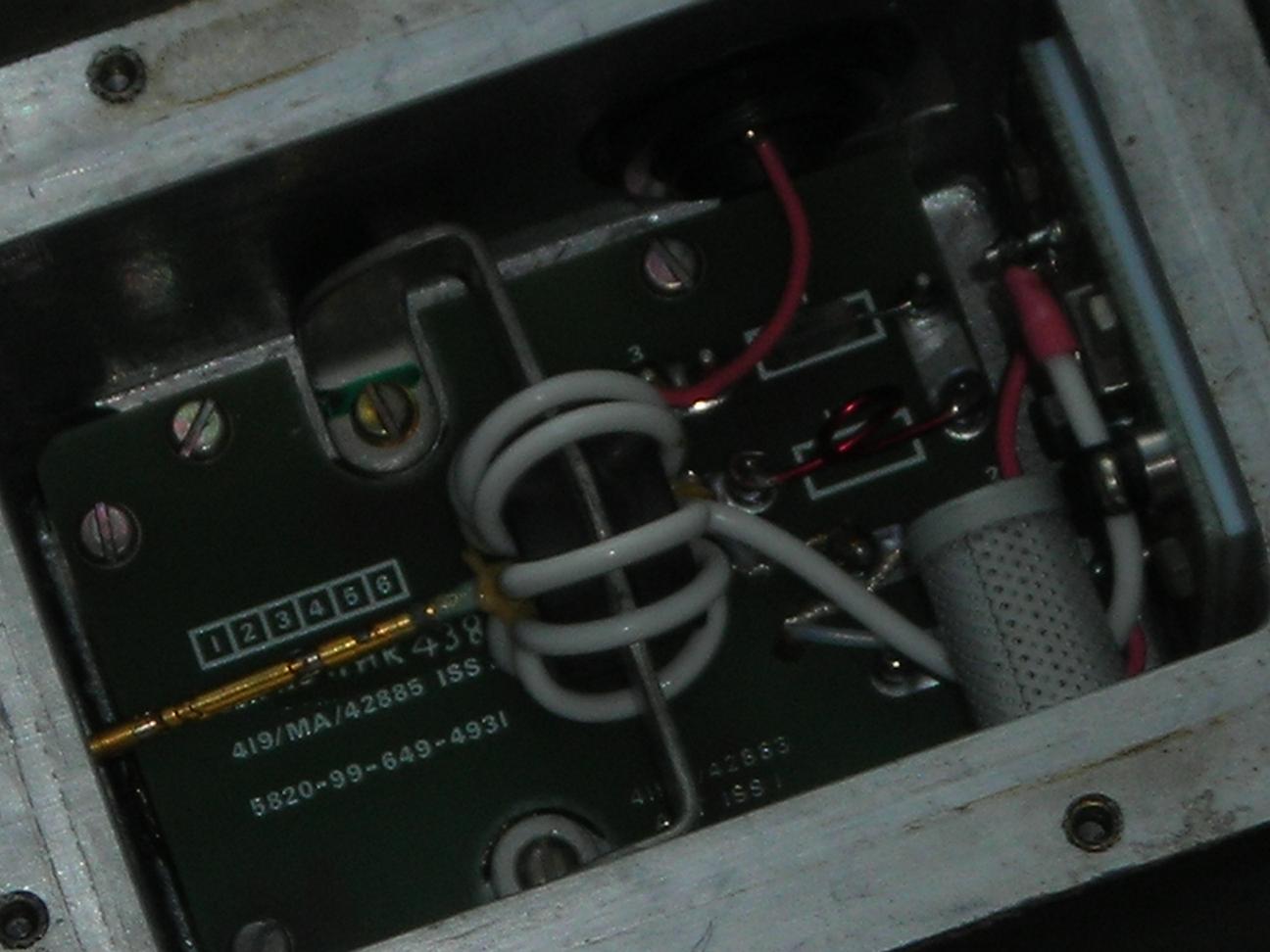
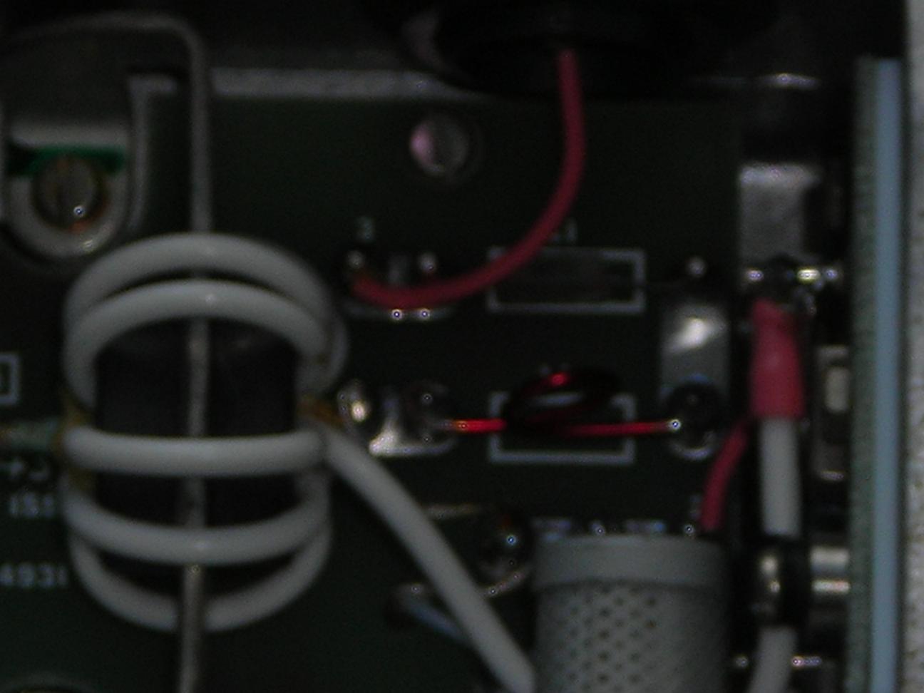
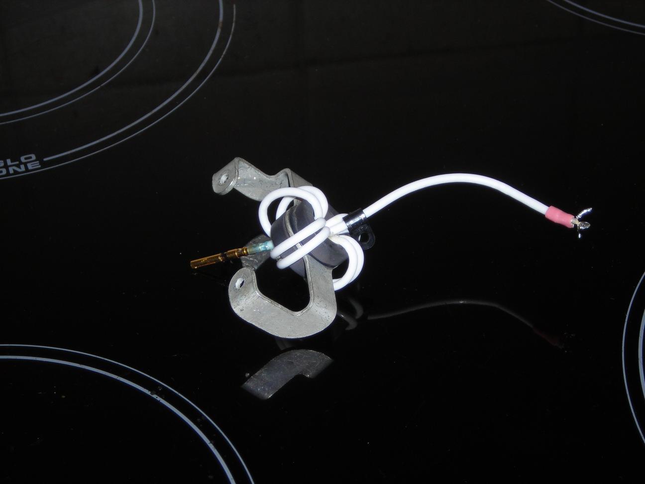
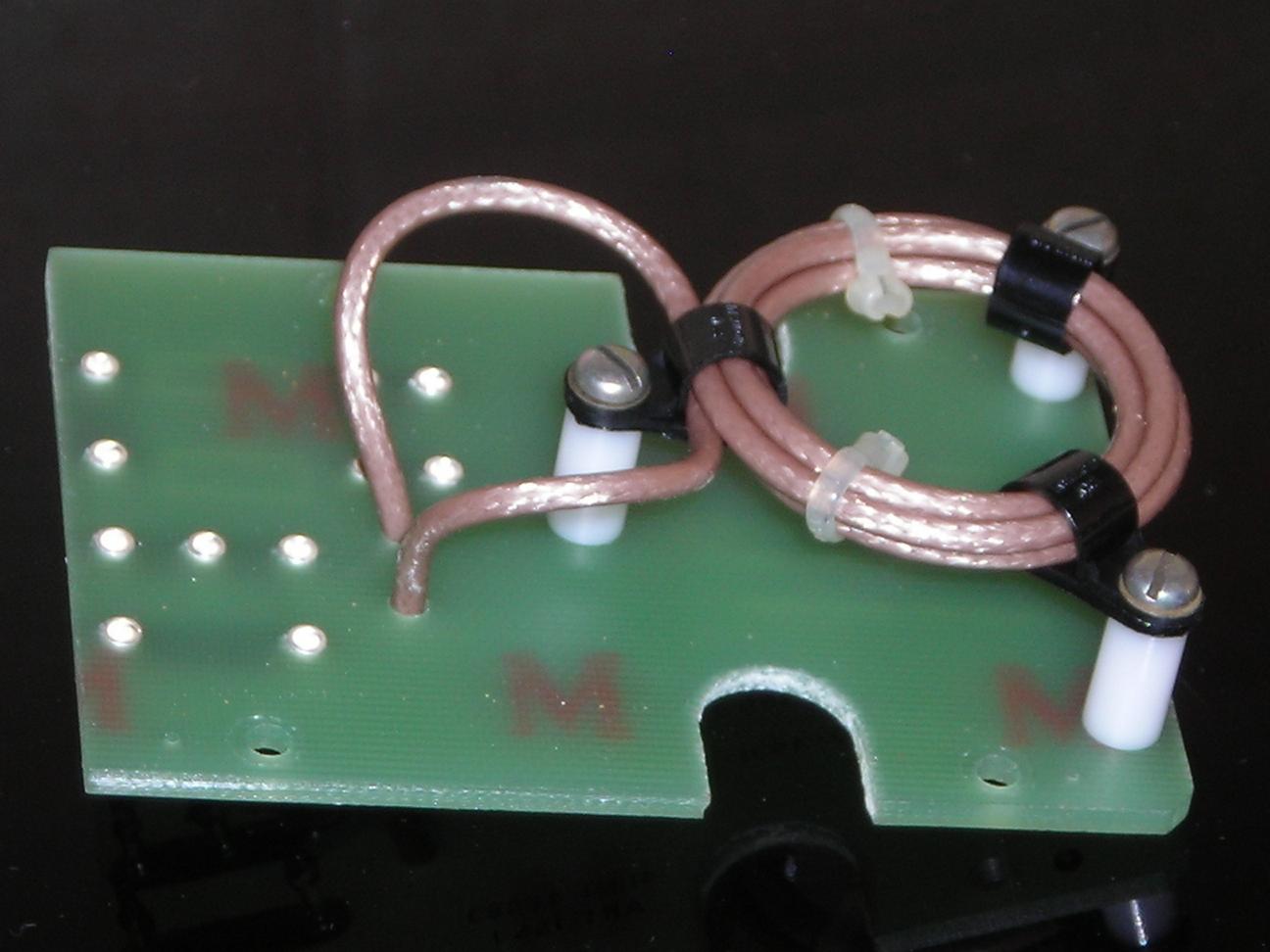
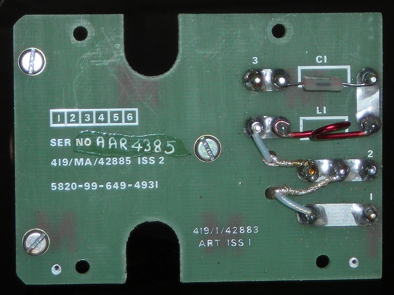
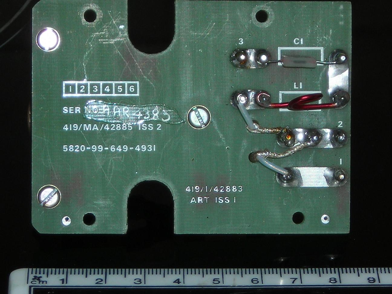
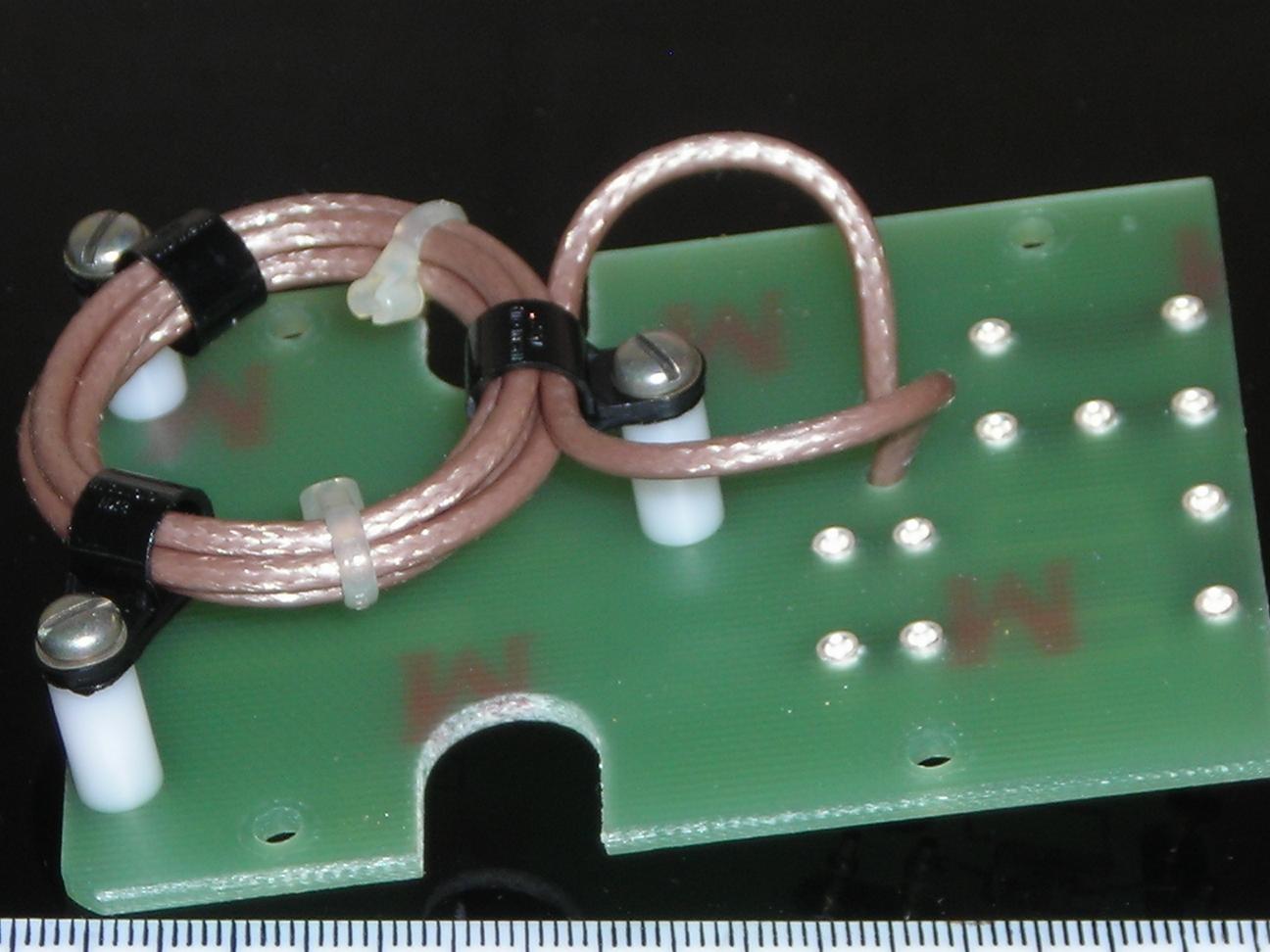
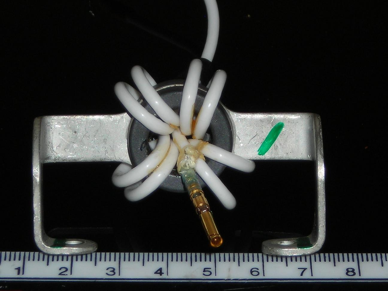
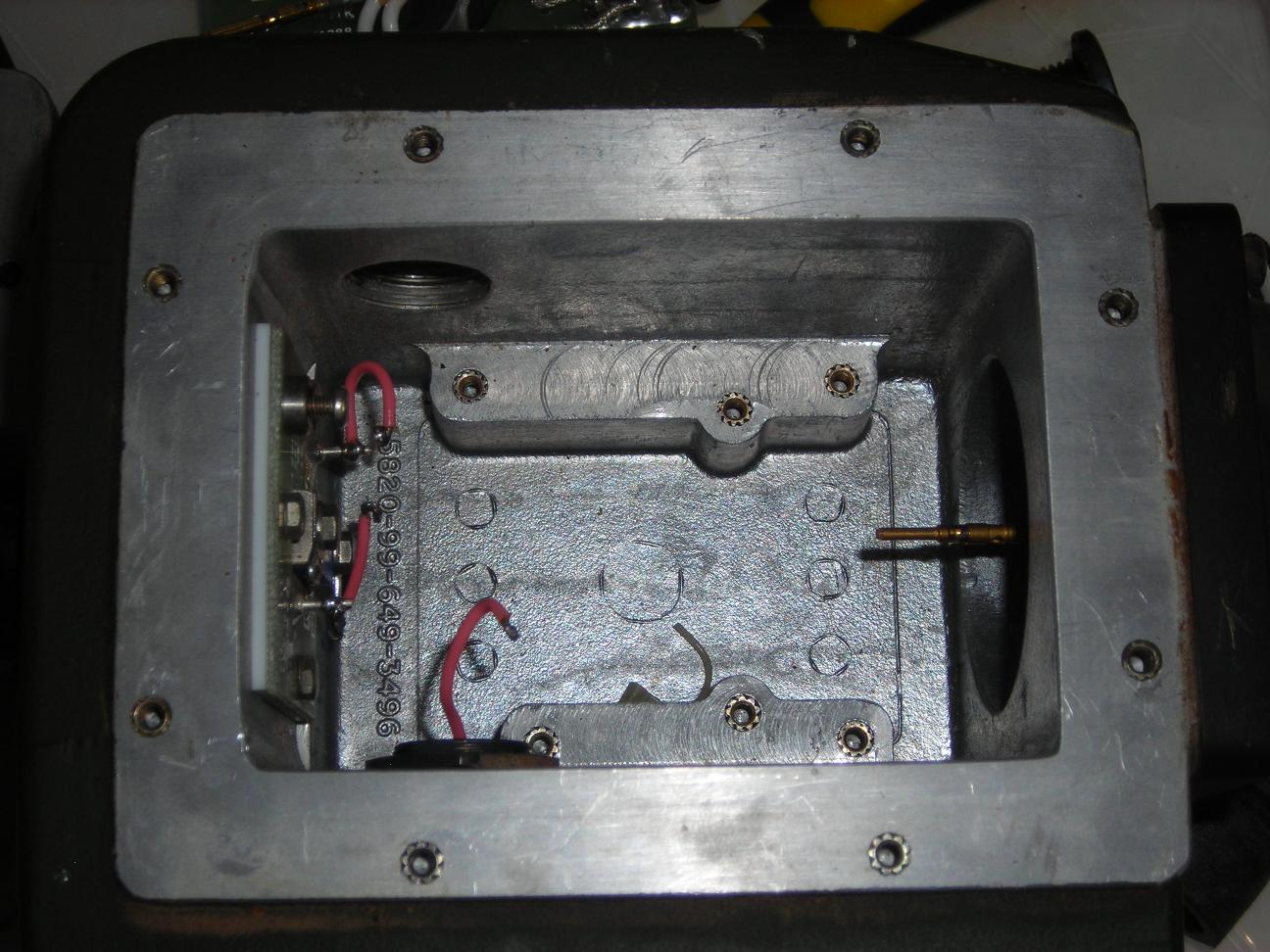
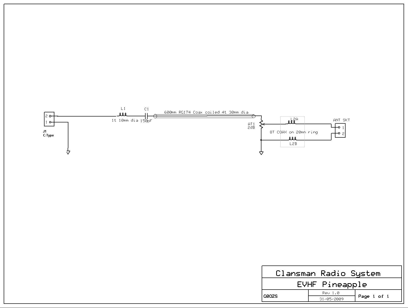
The EVHF is basically a sleeve dipole. The lower element is a tri-axal tube formed of alternate copper and fibreglass layers and seems to be rather fragile. The outside is the lower radiator of the dipole. The middle and inner conductors form a coaxial feed to the dipole "centre". The top two elements form a loaded or trapped whip (there is a bulge near the joint).The matching unit consists of a LC matching network, a coaxial transformer, a resistive attenuator and a choke balun. The aim of the attenuator is to reduce the reverse power reaching the transmitter on frequencies where the radiating elements are not well matched. The price for this is that a significant part of the forward power is converted to heat in the attenuator so a 50W VRC-353 station is reduced to less than 30W using the EVHF. There is a design tradeoff between having an inefficient antenna with broadband coverage and an efficient one that needs tuning - clearly the Clansman designers chose the former approach in this case - one might speculate that this is because it was intended to be at the top of an 8m mast when in use. The following is a schematic:
Specification:
| Frequency Range | 30.000 to 70 MHz |
| Maximum Power | 50 Watts |
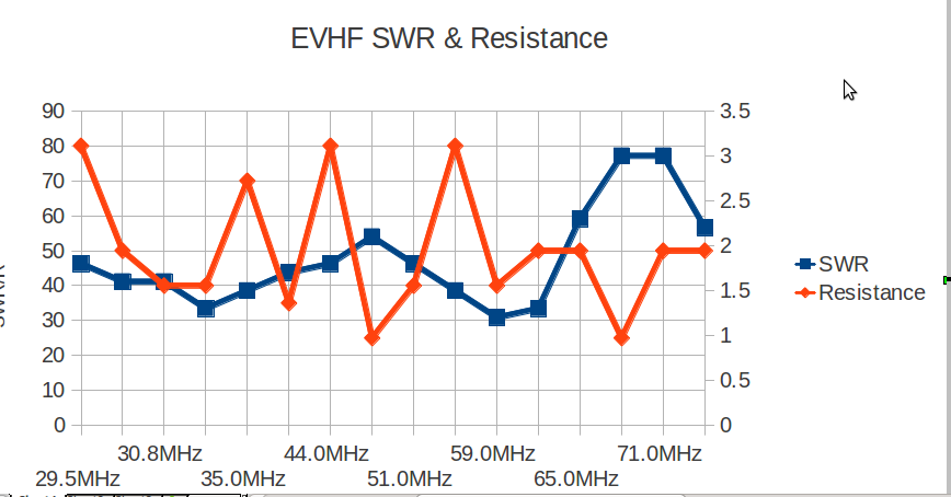
The following table documents readings made using an MFJ-259 antenna analyser over the 30 to 80MHz range. I've plotted the peaks and troughs in SWR plus spot frquencies on 10m, 4m and 6m. So joining the dots should give a fair approximation to the SWR vs Frequency graph.
| Frequency | SWR | Resistance |
| 29.5MHz | 1.8 | 80 Ohms |
| 30.0MHz | 1.6 | 50 Ohms |
| 30.8MHz | 1.6 | 40 Ohms |
| 33.0MHz | 1.3 | 40 Ohms |
| 35.0MHz | 1.5 | 70 Ohms |
| 40.0MHz | 1.7 | 35 Ohms |
| 44.0MHz | 1.8 | 80 Ohms |
| 49.0MHz | 2.1 | 25 Ohms |
| 51.0MHz | 1.8 | 40 Ohms |
| 55.0MHz | 1.5 | 80 Ohms |
| 59.0MHz | 1.2 | 40 Ohms |
| 61.0MHz | 1.3 | 50 Ohms |
| 65.0MHz | 2.3 | 50 Ohms |
| 70.0MHz | 3.0 | 25 Ohms |
| 71.0MHz | 3.0 | 50 Ohms |
| 79.0MHz | 2.2 | 50 Ohms |
Operating the EVHF
I have used my EVHF successfully with an RT353 and an 8m mast extended to around 5m. Operating at 15W power output on 4m I have had good contacts at 8 to 10 miles and marginal contacts at 15 miles.Using a RT352M I have had good results over a 6 mile path and marginal results at longer ranges on 6m.
I understand that with the EVHF at full height and a 50W VRC-353 station the expected range is 30 to 50 miles.