Carefully open the radio by removing the allen screws around the front and rear panels after noting the band switch position. A motorised screwdriver is recommended ! After all the screws are out and stored safely, gently pry open the case with a flat blade screwdriver and put the gaskets in safe storage - ideally pressed flat under a book. Gently reconnect the two halves and apply power via a battery extension cable and verify normal operation.
|
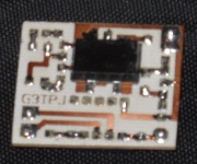
G3TPJ Board - Track Side
|
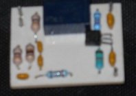
G3TPJ board - component side
|
 |
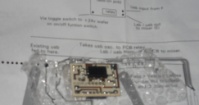
G3TPJ Board with instructions
|
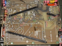
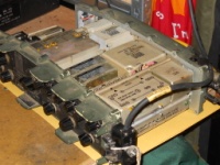
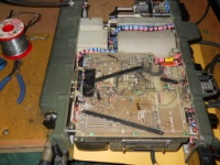
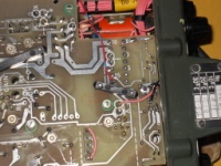
General view of main board before modification. Pin F and Pin X are lower left and Pin 16 is upper right (below \"15\")
|
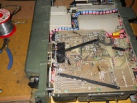
Preferred module locations are under cable loom at mid-left or in PCB cutout at middle right. G3TPJ boards need to be converted to single sided component mounting as per G8JNJ website to go in the cutout so the gap between module 5 and the rear turret under the cable loom is my preference.
|
|
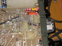
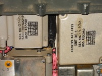
Pin 16 is between the black plastic bar and pin 15. It is +24V when the power switch is in the \"Battery Check\" position.
|
Pin F (1.7500 MHz in from oscillator module) is at the middle of the left edge of the PCB in this image. The two pins X above it are earthed.
|
G3TPJ board output (unloaded) is about 500mV allowing for x10 probe
|
|

Pin F is about 300mV in circuit allowing for an x10 probe
|
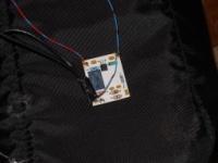
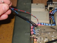
Connect power leads (blue is ground, red/blue is +24V) and coax tails to G3TPJ board. I linked coax earths to ground to ensure good RF ground so separate DC ground wire is likely redundant.
|
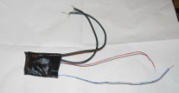
Board is wrapped in thick insulating tape after cutting down connection pins to avoid piercing the tape.
|
|
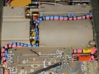
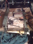
Place board between rear turret and PSU can.
|
Pull cable tails through and thread under D-Connectors at edge of board
|
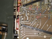
Cut track near pin F - ideally in 2 places a few mm apart and lift isolated track between after heating with the iron for a few seconds. Solder coax tails to either side of track cut at Pin F - relay input to Pin F and relay output to other side of cut. Solder ground wire and relay input coax braid to pins X. Relay output coax braid is cut short and insulated, the inner is on the mixer side of the track cut. Tape over the coax to ensure it won't foul the case when re-assembled.
|
|
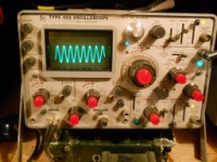
Once the track is cut and the coaxes are connected the normal USB CIO should be going via the relay on the G3TPJ board. This can be proved by testing for normal USB operation. On the bench, if a sig gen or another radio and Test Set Condition are available, a CW source tuned from 3.613 to 3.617 MHz should produce a rising audio tone as it passes a dial frequency of 3.615MHz in SSB HP mode.
|
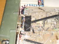
Close up of ground and RF connections.
|
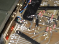
Close up showing track cut.
|
|
Connect +24V supply to board to pin 16 taking care to avoid shorts. Switch to \"Battery Check\" and test LSB operation. On the bench, if a sig gen or another radio and Test Set Condition are available, a CW source tuned from 3.613 to 3.617 MHz should produce falling audio tone as it passes a dial frequency of 3.615MHz in Battery Check mode. In SSB HP or SSB LP it should produce a rising tone as before. If a scope is available the signal on the mixer side of the track cut will be a clean 300mV sine wave for USB and a slightly AF modulated 500mV sine wave on LSB - I think the original source has a higher impedance and the G3TPJ board unbalances the mixer, but there are no obvious ill effects. On Air testing suggests that the TX AF bandwidth is less on LSB than USB (possibly due to variation in filter spec from the set that G4OEP used to derive the 1.7468MHz LSB CIO frequency) and quieter on RX (again due to loss of HF audio?) but good copy both ways is possible.
|
Tape over new connections on the main board to avoid shorts to case when reassembled.Then separate the halves and put them back in the case. Do not turn the band selector while the halves are separated. Remember to replace the gaskets during re-assembly. It is recommended to start by fitting 2 screws at diagonally opposite corners of each side panel and testing the radio, before putting back the rest.
|
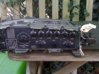
Reassembled Radio
|
|
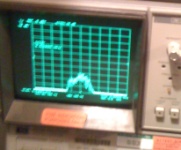
USB TX spectrum of G0OZS humming
|
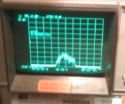
LSB TX Spectrum of G0OZS Humming
|