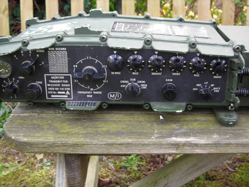
The RT320
The RT320 is the standard HF manpack of the Clansman family (the RT319
being a later set made in small quantities for special forces use). The
RT320 was manufactured by Plessey and makes extensive use of MSI linear
integrated circuits and 3V logic. The set covers 2 to 30MHz in 100Hz
steps in CW, AM and SSB and has an inbuilt ATU for whip and long wire
antennas. Output power is 5W (low) and 30W (high) and the RT320 is
noted for receiver sensitivity - based on Clansman test set attenuator
settings it is at least 4dB better than the RT321.
(More RT320 Photos)
Index
Operating Guide
This is a one page guide to set up and operating of the UK/PRC320
intended to be printed and laminated for use in the field.
(Click to view full size)
Operating Experience
To date my best results with the RT320 have been on 14MHz/20M with a long wire
antenna and a quarter wave counterpoise. I've managed QSOs with Sicily on low
power and Virginia USA on high power, and copied a ZL station 59, but I find
that the radio is not powerful enough on its own to crack pile-ups on HF or
break in to the 80M AM VMARS net without a good antenna. I've never yet had
a reply to calls made using the 2.5M whip - I think that is only really useful
for local ground-wave operation or receive use.
Operating Hints
- The most common operating error is to set the frequency without moving
the band switch. This will result in a continuous high pitched tone -
normally the 320 will emit this unready tone for a few seconds when
powered up or when changing bands before the normal receiver output
is heard.
Variants
There are at least 3 variants of the RT320:
- The UK/PRC320: The British army version, with USB, CW and AM in 100Hz tuning steps
- The RT320/L: A Yugoslav license-built set with LSB, CW and AM
- The RT320/1: A Plessey export radio with USB, LSB, CW and AM but only 1KHz tuning steps
The RT320/2 is a closely related vehicle or fixed set comprising a repackaged
RT320 in a rectangular case and a separate 100W amplifier.
Circuit description
The RT320 is a single conversion superhet receiver with an IF of 1.75MHz. There
are separate IF filters for CW/AM and SSB - there is a sideband inversion so
an LSB filter is used for USB radios and a USB filter for LSB radios, and the
320/1 appears to have one each of LSB and USB so presumably both were in
circuit for AM. The transmit path is essentially the reverse of receive,
with the output being the difference of LO and 1.75MHz. The radio has a
turret tuner operated by the band switch, with separate front end tuning
and oscillator boards in circuit for each of 6 bands.
The case contains essentially separate transceiver and ATU parts
connected by an external BNC to BNC patch lead. Dipole or other 50-ohm
antennas may be connected to the transceiver output BNC, and wire antennas
can be connected to the ATU antenna terminal. Metering is at the transceiver
output so is effective for both ATU connected and coax connected antennas.
Unlike the RT321 the meter is operational only in transmit - it is not
an S-meter. The ATU is a permeability tuned type with switched capacitors.
The RT320 requires a well smoothed 20 to 28V supply from either a battery
or a regulated PSU - it is not suitable for direct operation from a 24V
vehicle supply and in vehicles a DCCU charger was used to float charge
the battery. Internally a highly efficient switch mode PSU provides 3V,
6V, 12V and 110V supplies - 3 and 6V are derived from 12v. The main
cause of failure on the RT320 is PSU module 5 - in particular the
125V rated tantalum capacitors in the 110V supply used for the varicap
tuning voltage. Early signs of failure include failure to tune at the
upper end of each band and chirp on CW or when switching between TX and
RX modes.
Mechanically the RT320 is built in two halves attached to the front and
rear panels. The synthesiser, audio and IF parts and most of the ATU are
attached to the front panel, while the PA and the RF tuning part of the
turret tuner are attached to the rear panel.
Most of the screened modules are connected to a wiring harness by micro
D-Connectors, in some cases with coaxial inserts.Dismantling involves
removing the allen (hex socket head) screws around the edges of the
front and rear panels, gently breaking the seals, and then pulling the
two halves out of the shell. When re-assembling remember that the rear
half of the turret connects to the front half using a screwdriver-like
coupling and the band switch must be in the same position as it was when
the set was opened for them to mate properly.
Although the UK/PRC320 is only capable of upper sideband operation
it is relatively easy to add a 2nd carrier insertion oscillator at
1.7468MHz with 20mV output so the same filter can be used for LSB.
This is documented at the LSB page
on this site. A kit is now available from G4IQE and G3TPJ. I have
fitted one and the photographic record is
here.
Last Updated 12-Feb-2012 by G0OZS
Copyright © G0OZS 2009-2012.